文章目录(Table of Contents)
简介
这是使用 SUMO 来进行仿真的第二篇内容。在上一篇的例子中,我们使用 SUMO 完成了一个简单的例子,了解了 node 和 edge 文件,并制作了一个简单的路网。这一篇会就上面的问题进行展开,进一步了解 node 和 edge 文件(我们会创建一个稍微复杂的环境)。
Network的创建,关于node和edge的用法;- Edge Type 的使用,设置 edge 的属性,来简化 edge 文件;
- Road Access Permissions(规定道路允许通行的车辆);
- 利用 Open Street Map 来生成路网;
参考资料
- 知乎上关于 sumo 的一个教程文章, 还是很不错的:
- 本文的相关代码参考 Github 仓库,SUMO Tutorial(
Node_Edge_Introduce文件夹部分)
Network 文件生成
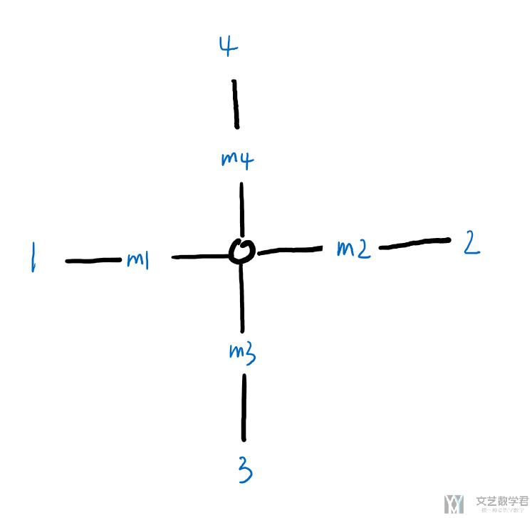
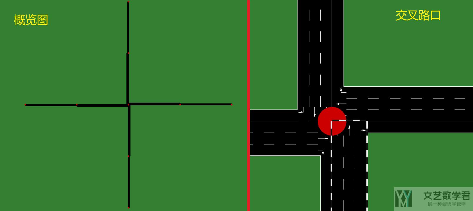
这一部分参考自,Networks/PlainXML。首先我们创建 net.xml。整个 network 的结构如下所示,共有 9 个节点(中心节点+周围的 8 个节点):
Node 的相关说明 (Node Descriptions)
按照上面的示意图,我们新建 ".nod.xml" 来描述上面的路网结构。完整文件如下所示:
- <nodes> <!-- The opening tag -->
- <node id="0" x="0.0" y="0.0" type="traffic_light"/> <!-- def. of node "0" -->
- <node id="1" x="-500.0" y="0.0" type="priority"/> <!-- def. of node "1" -->
- <node id="2" x="+500.0" y="0.0" type="priority"/> <!-- def. of node "2" -->
- <node id="3" x="0.0" y="-500.0" type="priority"/> <!-- def. of node "3" -->
- <node id="4" x="0.0" y="+500.0" type="priority"/> <!-- def. of node "4" -->
- <node id="m1" x="-250.0" y="0.0" type="priority"/> <!-- def. of node "m1" -->
- <node id="m2" x="+250.0" y="0.0" type="priority"/> <!-- def. of node "m2" -->
- <node id="m3" x="0.0" y="-250.0" type="priority"/> <!-- def. of node "m3" -->
- <node id="m4" x="0.0" y="+250.0" type="priority"/> <!-- def. of node "m4" -->
- </nodes> <!-- The closing tag -->
在上面的例子中,id 为 0 的节点是整个十字路口的中心节点,也是红绿灯。可以看他的 type 是 traffic_light,表示这个 node 是信号灯。 于是整个 node 的关系如下图所示(和上面的结构是一样的):
Edge 的相关说明 (Edge Descriptions)
在有了上面的 Node 的定义之后,下面需要定义 Edge。下面是一个基础的 Edge 文件的定义,对于每一个 edge 来说,最基础的是需要包含:
- id, 每一个 edge 独特的标志, 用来找到指定的 edge;
- from, to,from 和 to 是与上面的 node 的 id 对应的)
- priority,优先级, 在转弯处有用;
- numLanes,这个edge上包含多少个车道;
- speed,车道的车速,也就是限速;
我们新建一个「hello.edg.xml」,并输入以下的内容:
- <edges>
- <edge id="1fi" from="1" to="m1" priority="2" numLanes="2" speed="11.11"/>
- <edge id="1si" from="m1" to="0" priority="3" numLanes="3" speed="13.89"/>
- <edge id="1o" from="0" to="1" priority="1" numLanes="1" speed="11.11"/>
- <edge id="2fi" from="2" to="m2" priority="2" numLanes="2" speed="11.11"/>
- <edge id="2si" from="m2" to="0" priority="3" numLanes="3" speed="13.89"/>
- <edge id="2o" from="0" to="2" priority="1" numLanes="1" speed="11.11"/>
- <edge id="3fi" from="3" to="m3" priority="2" numLanes="2" speed="11.11"/>
- <edge id="3si" from="m3" to="0" priority="3" numLanes="3" speed="13.89"/>
- <edge id="3o" from="0" to="3" priority="1" numLanes="1" speed="11.11"/>
- <edge id="4fi" from="4" to="m4" priority="2" numLanes="2" speed="11.11"/>
- <edge id="4si" from="m4" to="0" priority="3" numLanes="3" speed="13.89"/>
- <edge id="4o" from="0" to="4" priority="1" numLanes="1" speed="11.11"/>
- </edges>
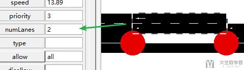
这里每一个 edge 包含多个 lane (车道,通过参数「numLanes」进行设置)。我们以上面的 node 0, node m4, node 4 这三个 node 之间的 edge 作为例子来进行简单的说明. 他们整体的车道关系如下所示:
- 从
node 4到node m4方向, 有 2 个车道; - 从
node m4到node 0方向, 有 3 个车道; - 从
node 0到node 4方向, 有 1 个车道;
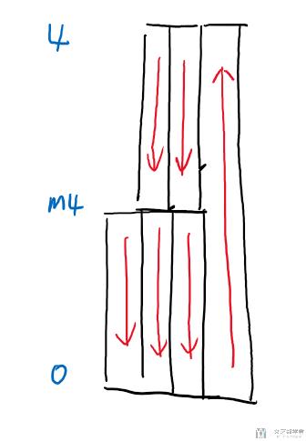
所以他们上面 edge 的关系如下所示,这里设置的车道数与上面解释的是一样的:
- <edge id="4fi" from="4" to="m4" priority="2" numLanes="2" speed="11.11"/> <!-- 4->m4, 2 车道 -->
- <edge id="4si" from="m4" to="0" priority="3" numLanes="3" speed="13.89"/> <!-- m4->0, 3 车道 -->
- <edge id="4o" from="0" to="4" priority="1" numLanes="1" speed="11.11"/> <!-- 0->4, 1 车道 -->
在有了 node 和 edge 之后,我们就可以生成 network 文件了。我们通过下面的命令进行生成:
netconvert --node-files=hello.nod.xml --edge-files=hello.edg.xml --output-file=hello.net.xml
成功运行上面的命令后,会生成 hello.net.xml 文件。我们使用 NetEdit 打开该文件,可以看到如下所示的路网结构,与上面我们介绍的结构是一样的:
Edge Type
上面我们对于每一个 edge 是单独设置他的属性的。可以看到其中有些属性是重复的,所以我们可以先定义 edge type,接着将 edge type 用在每一个 edge 上面。我们将 edge type 存储在 cross3l.typ.xml 的文件中,如下所示:
- <types>
- <type id="a" priority="3" numLanes="3" speed="13.889"/>
- <type id="b" priority="2" numLanes="2" speed="11.111"/>
- <type id="c" priority="1" numLanes="1" speed="11.111"/>
- </types>
接着定义 edge 文件。该文件还是保存为 cross3l.edg.xml 文件。 所有 edge 的类型通过 type 来进行定义(这里就不需要说明每一个 edge 的 「numLanes」、「speed」等属性了):
- <edges>
- <edge id="1fi" from="1" to="m1" type="b"/>
- <edge id="1si" from="m1" to="0" type="a"/>
- <edge id="1o" from="0" to="1" type="c"/>
- <edge id="2fi" from="2" to="m2" type="b"/>
- <edge id="2si" from="m2" to="0" type="a"/>
- <edge id="2o" from="0" to="2" type="c"/>
- <edge id="3fi" from="3" to="m3" type="b"/>
- <edge id="3si" from="m3" to="0" type="a"/>
- <edge id="3o" from="0" to="3" type="c"/>
- <edge id="4fi" from="4" to="m4" type="b"/>
- <edge id="4si" from="m4" to="0" type="a"/>
- <edge id="4o" from="0" to="4" type="c"/>
- </edges>
之后我们在生成 cross3l.net.xml 的时候, 只需要加上cross3l.typ.xml文件即可。我们还是使用 netconvert 来生成最终的 netfile。
- netconvert --node-files=cross3l.nod.xml --edge-files=cross3l.edg.xml --type-files=cross3l.typ.xml --output-file=cross3l.net.xml
Road Access Permissions
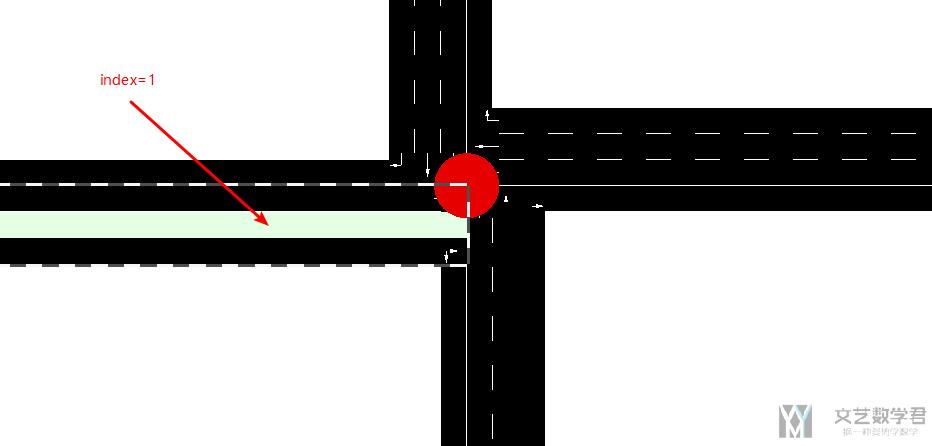
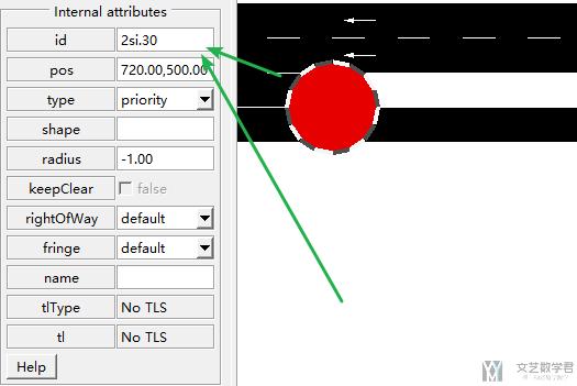
我们还可以对其中某个 edge 其中的 lane 进行额外的设置。例如可以定义 disallow 和 allow。当disallow='all' 的时候,这个可能表示是绿化带等,不能通行。这里 disallow 和 allow 后面接车辆的类型(list of vehicle classes)。例如可以写 disallow="passenger taxi"。
我们对上面的 cross3l.edg.xml 文件进行修改。我们修改 edge_id=1si,本来他是有三个车道的,我们将其中第二个车道设置为无法通行:
- ... previous definitions ...
- <edge id="1si" from="m1" to="0" type="a">
- <lane index="1" disallow="all"/>
- </edge>
- <edge id="1o" from="0" to="1" type="c"/>
- ... further definitions ...
上面 id='1si' 这个 edge 上,index=1(第二个 lane 上面无法通行)。最后效果如下:
参考资料,Road access permissions (allow, disallow)
Road Segment Refining
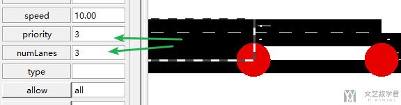
对于同一段 edge,我们可以对不同的位置来进行分别定义。例如下面的例子(一种比较常见的用法):
- ... previous definitions ...
- <edge id="2si" from="m2" to="0" priority="3" numLanes="3" speed="13.89">
- <split pos="0" lanes="0 1"/>
- <split pos="30" lanes="0 1 2" speed="10"/>
- </edge>
- ... further definitions ...
下面是按照上面的文件生成的 network。下面的 edge 有 3 个 lane。第一个 split 是从开始位置,到 0m 的位置,加一个 node(还是开始位置)。第二个 split 是从开始位置到 30m 的位置, 加一个 node (命名方式是<EDGE_ID>.<POSITION)。新增的 node 如下所示, 可以看到他的 ID 就是 edge_id+position。
node 与 node 之间只包含参数 lanes 中的 lane。例如从起点 0m 到 30m 的这一段,就只包含 2 个 lane。
从 30m 到终点那一段, 速度就是被限制在 10, 上面 0-30 这一段速度是没有限制的. 但是这一段numLanes是=3, 因为上面 lanes="0 1 2"。
生成网格状地图
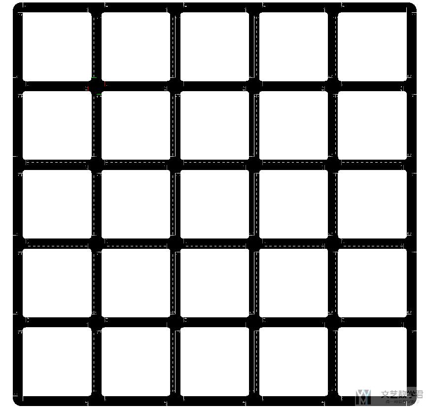
对于一些比较复杂的 network,我们就不能自己去手写 node 和 edge 文件了。下面是一个使用python 生成网格状 network 的例子(可以举一反三)。下面可以生成 node 和 edge 文件。
首先是生成 node 文件,我们会生成若干个 100100 的小方格,每一个格点就是一个 node。这里我们生成一个 66 一共 36 个 node:
- # 生成Node文件, 从左下角(0,0)开始生成的
- with open('cross.nod.xml', 'w') as file:
- file.write('<nodes> \n')
- for i in range(6):
- for j in range(6):
- file.write('<node id="node%d" x="%d" y="%d" type="priority" /> \n' %(i*6+j, i*100, j*100))
- file.write('</nodes> \n')
接着我们生成 edge 文件,我们需要将上面的 36 个 node 连接起来。这里所有的 edge 都是由两个 Lane 组成,速度都是 40。
- # 生成edge文件
- with open('cross.edg.xml', 'w') as file:
- file.write('<edges> \n')
- for i in range(6):
- for j in range(6):
- k=0
- if i > 0:
- file.write('<edge id="edge%d_%d" from="node%d" to="node%d" priority="75" numLanes="2" speed="40" /> \n' % (i*6+j,k,i*6+j,(i-1)*6+j))
- k=k+1
- if i < 5:
- file.write('<edge id="edge%d_%d" from="node%d" to="node%d" priority="75" numLanes="2" speed="40" /> \n' % (i*6+j,k,i*6+j,(i+1)*6+j))
- k=k+1
- if j > 0:
- file.write('<edge id="edge%d_%d" from="node%d" to="node%d" priority="75" numLanes="2" speed="40" /> \n' % (i*6+j,k,i*6+j,i*6+j-1))
- k=k+1
- if j < 5:
- file.write('<edge id="edge%d_%d" from="node%d" to="node%d" priority="75" numLanes="2" speed="40" /> \n' % (i*6+j,k,i*6+j,i*6+j+1))
- k=k+1
- file.write('</edges> \n')
之后通过 netconvert 来生成 network 文件.
- netconvert --node-files=cross.nod.xml --edge-files=cross.edg.xml --output-file=cross.net.xml
最后生成的 network 如下所示:
Network 文件说明
下面简单介绍一下生成的 network 文件。在生成的 network 中, 会包含 direction,下面是一些缩写与全称的对应关系。
- “s” = straight
- “t” = turn
- “l” = left
- “r” = right
- “L” = partially left
- “R” = partially right
- “invalid” = no direction
从 Open Street Map 生成路网
上面我们介绍了通过 Netedit 或是直接使用脚本生成路网。有的时候我们需要根据真是的地图来生成路网。这个时候就需要用到 OpenStreetMap。下面是两个参考链接。
- Open Street Map,OSM 的官网;
- SUMO for OpenStreetMap,SUMO 与 OSM 联动的例子;
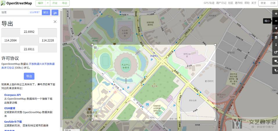
获取路网
首先我们打开 Open Street Map 并选择自己感兴趣的区域进行截取。如下图所示,我们进行截取并导出,最终会保存为 .osm 的文件:
路网转换
直接导出的格式是 osm,我们需要将其转换为 sumo 支持的 net.xml 的格式。可以使用 netconvert 进行转换。具体转换的命令如下所示:
- netconvert --osm-files map.osm --geometry.remove --ramps.guess --junctions.join --tls.guess-signals --tls.discard-simple --tls.join --tls.default-type actuated -o sumo.net.xml
上面的命令的意思如下所示:
- --geometry.remove : Simplifies the network (saving space) without changing topology
- --ramps.guess : Acceleration/Deceleration lanes are often not included in OSM data. This option identifies roads that likely have these additional lanes and adds them
- --junctions.join : See #Junctions,这个可以将附近的交叉路口进行合并;
- --tls.guess-signals --tls.discard-simple --tls.join : See #Traffic_Lights
- --tls.default-type actuated : Default static traffic lights are defined without knowledge about traffic patterns and may work poorly in high traffic
转换之后其实还是不能直接使用的,需要进行一些修改,例如:
- 删除多余的道路,例如人行道,地铁等;
- 修改车道数,可以根据卫星图片进行校对;
- 微信公众号
- 关注微信公众号
-

- QQ群
- 我们的QQ群号
-


评论